
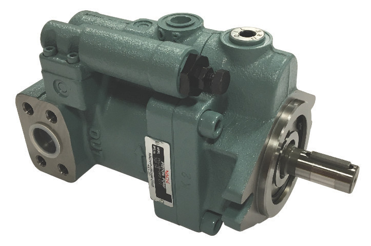
PVS Series
Compare models — PVS Series
Compare all 974 listed models. Configuration descriptions are quoted from the listed manufacturer information; confirm performance and complete options in the linked catalog.
Loading model comparison…
| Exact model | Part number | Listed pump type / configuration | Manufacturer reference |
|---|
PVS configuration selection guide
Compare the catalog configurations below. These groups are not complete order codes. Confirm the full model, design, control and connection details in the catalog.
| Catalog configuration | Catalog displacement (cm³/rev) | No-load flow at 1800 rpm (gpm) | Catalog design |
|---|---|---|---|
| PVS-0B-8 | 8 | 3.8 | E30 |
| PVS-1B-16 | 16.5 | 7.8 | E13 |
| PVS-1B-22 | 22 | 10.5 | E13 |
| PVS-2B-35 | 35 | 16.6 | E13 |
| PVS-2B-45 | 45 | 21.5 | E13; E20 for the catalog 45N3 configuration |
Values apply to the B flange configurations and designs shown. No-load flow depends on speed; operating flow depends on conditions. The 1B-16 specification table lists 16.5 cm³/rev. PVS manufacturer catalog
Compare control types (8 catalog choices)
| Catalog symbol | Control choice | Selection difference |
|---|---|---|
| N | Manual pressure compensation | Discharge reduces at the pressure setting to hold pressure. |
| P | Remote pressure compensation | External pilot pressure sets discharge pressure. |
| NQ | Two-pressure, two-flow control | Two-stage discharge using the built-in sequence arrangement. |
| RS / RA | Solenoid cutoff control | Unload function switches when pump output is unnecessary. |
| WS / WA | Two-pressure control | Solenoid switching selects two pressure levels. |
| RQS / RQA | Two-pressure, two-flow with cutoff | Two-stage output plus solenoid unloading. |
| CS / CA | Two-cutoff control | Solenoid-operated selection of two pressure-flow characteristics. |
| R | Load sensing | Control responds through its load-sense pilot arrangement. |
Choices depend on size, design and port arrangement. PVS-0B-8 excludes NQ, RS, WS, RQS and CS. Axial-port Z versions of 1B/2B exclude NQ, RQS and CS. Confirm permitted combinations in the catalog.
Compare PVS-0B-8N models — E30 design
| Model | Displacement | Pressure adjustment interval | Mount, control and piping |
|---|---|---|---|
| PVS-0B-8N0-E30 | 8 cm³/rev | 286–500 psi | Flange mount; pressure compensation; E30 / SAE piping |
| PVS-0B-8N1-E30 | 8 cm³/rev | 286–1000 psi | Flange mount; pressure compensation; E30 / SAE piping |
| PVS-0B-8N2-E30 | 8 cm³/rev | 429–2000 psi | Flange mount; pressure compensation; E30 / SAE piping |
| PVS-0B-8N3-E30 | 8 cm³/rev | 429–3000 psi | Flange mount; pressure compensation; E30 / SAE piping |
These adjustment intervals come from the exact manufacturer model pages; they are not peak-pressure ratings.
Compare through-shaft models with documented features (12 models)
Capacity labels below repeat the product descriptions. The descriptions state cc without a per-revolution basis. Pressure limits, piping and design-specific compatibility require confirmation.
| Model | Capacity label in description | Shaft configuration | Control in description |
|---|---|---|---|
| PVS-0B-8N3-K-E5737B | 8cc (/rev not stated) | Keyed shaft | Standard Compensator |
| PVS-1B-16N3-K-E5737B | 16cc (/rev not stated) | Keyed shaft | Standard Compensator |
| PVS-1B-22N3-K-E5737B | 22cc (/rev not stated) | Keyed shaft | Standard Compensator |
| PVS-2B-35N3-K-E5737B | 35cc (/rev not stated) | Keyed shaft | Standard Compensator |
| PVS-2B-45N3-K-E5737B | 45cc (/rev not stated) | Keyed shaft | Standard Compensator |
| PVS-0B-8N3-S-E5737B | 8cc (/rev not stated) | Spline shaft | Standard Compensator |
| PVS-1B-16N3-S1-E5737B | 16cc (/rev not stated) | Spline shaft | Standard Compensator |
| PVS-1B-16N3-S3-E5737B | 16cc (/rev not stated) | Spline shaft | Standard Compensator |
| PVS-2B-35N3-S1-E5737B | 35cc (/rev not stated) | Spline shaft | Standard Compensator |
| PVS-2B-35N3-S3-E5737B | 35cc (/rev not stated) | Spline shaft | Standard Compensator |
| PVS-2B-45N3-S1-E5737B | Not stated | Spline shaft | Not stated |
| PVS-2B-45N3-S3-E5737B | Not stated | Spline shaft | Not stated |
The tables compare selected models with documented details. Use the existing model list below for other PVS variants; their model-specific ratings remain to be confirmed.
Manufacturer technical resources
Manufacturer engineering drawings (DWG / DXF)
Drawings cover the model patterns and design numbers shown in each drawing. Match the full model and design number to your configuration.
- C-PVS2CS_E — PVS-2A(B)-*C*S*-12/20 : DWG / DXF
- C-PVS2RQ_E — PVS-2A(B)-*RQ*S*-12/20 : DWG / DXF
- C-PVS2WZ_E — PVS-2A(B)-*W*S*-Z-12/20 : DWG / DXF
- C-PVS2WS_E — PVS-2A(B)-*W*S*-12/20 : DWG / DXF
- C-PVS2RZ_E — PVS-2A(B)-*R*S*-Z-12/20 : DWG / DXF
- C-PVS2RS_E — PVS-2A(B)-*R*S*-12/20 : DWG / DXF
- C-PVS2PZ_E — PVS-2A(B)-*P*-Z-12/20 : DWG / DXF
- C-PVS2NQ_E — PVS-2A(B)-*N*Q*-12/20 : DWG / DXF
- C-PVS2P_E — PVS-2A(B)-*P*-12/20 : DWG / DXF
- C-PVS2NZ_E — PVS-2A(B)-*N*-Z-12/20 : DWG / DXF
- C-PVS1CS_E — PVS-1A(B)-*C*S*-12 : DWG / DXF
- C-PVS2N_E — PVS-2A(B)-*N*-12/20 : DWG / DXF
- C-PVS1RQ_E — PVS-1A(B)-*RQ*S*-12 : DWG / DXF
- C-PVS1WZ_E — PVS-1A(B)-*W*S*-Z-12 : DWG / DXF
- C-PVS1WS_E — PVS-1A(B)-*W*S*-12 : DWG / DXF
- C-PVS1RZ_E — PVS-1A(B)-*R*S*-Z-12 : DWG / DXF
- C-PVS1RS_E — PVS-1A(B)-*R*S*-12 : DWG / DXF
- C-PVS1NQ_E — PVS-1A(B)-*N*Q*-12 : DWG / DXF
- C-PVS1PZ_E — PVS-1A(B)-*P*-Z-12 : DWG / DXF
- C-PVS1NZ_E — PVS-1A(B)-*N*-Z-12 : DWG / DXF
- C-PVS1P_E — PVS-1A(B)-*P*-12 : DWG / DXF
- C-PVS1N_E — PVS-1A(B)-*N*-12 : DWG / DXF
- C-PVS0P_E — PVS-0A(B)-8P*-30 : DWG / DXF
- C-PVS0N_E — PVS-0A(B)-8N*-30 : DWG / DXF


